Fusion 360 Sheet Metal Variable Flange

My Opinions On Sheetmetal Autodesk Community Community Archive Read Only

Solved Project Sheet Metal Flange To Plane Autodesk Community Inventor

Solved Change Sheet Metal Bend Radius Autodesk Community Inventor

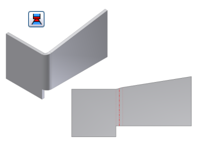
Solved Help With Corner Seam On A Compound Angle Autodesk Community Inventor

Pin Em Solidworks

Flange Feature In Inventor 2015 Youtube
Let s show how to create sheet metal bends folds flange unfold flat pattern and more.
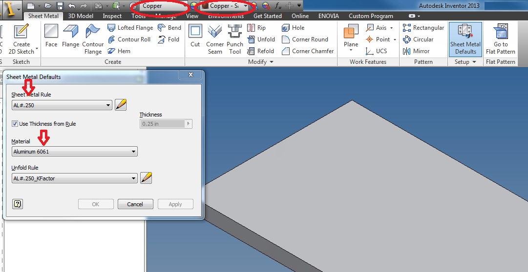
Fusion 360 sheet metal variable flange. Share and vote on ideas for future product releases. The example part we will be designing is a bracket for the hitec hs 5065mg servo. This article covers how to get started with sheet metal design in fusion 360. In the browser the part icon has changed to a sheet metal icon and the sheet metal rule appears below the document settings.
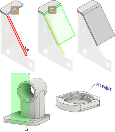
However a limitation is imposed for sheet metal bodies which prevents this action. We just want to be able to get the job done. Fusion 360 has released the sheet metal modeling environment. To add additional edges make sure to hold control or command and the flange will adjust accordingly.
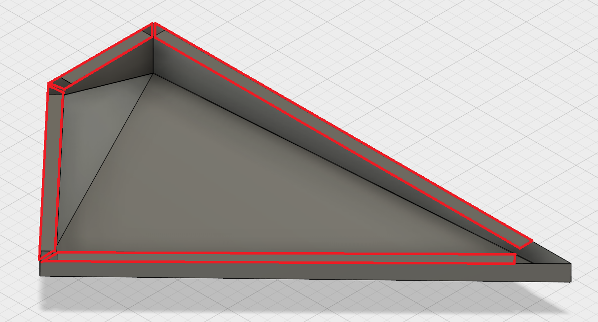
Beginners watch fusion training videos to prepare for class projects intermediate learners use them to build 3d design skills and advanced students review them for a refresher. The command is aware of what is being selected and will automatically switch to the right command. Where there are breaks in the original edges the flange will automatically miter. User are unsure how to edit the extent of a flange within the sheet metal module of fusion.
Get free video training in fusion 360. Visit fusion 360 forum. To make this design we will cover creating a base flange adding bends folding and unfolding the design virtually adding holes and other features and creating bending patterns that. Design careers start with free fusion 360 software training no experience required.
This must be done through command dialog box. Fusion automatically creates a flange starting from the modeled edge that follows the sketch contour.

Solved Sheetmetal Autodesk Community Inventor
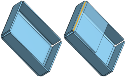
Solved Sheet Metal Flange Miter With Angle Autodesk Community Fusion 360

Inventor Sheet Metal Countour Flanges Youtube

Multiple Flanges On Sheet Metal Face Autodesk Community Inventor

Inventor Holes In A Sheetmetal Curve Youtube

Corner Seam In Sheet Metal Parts Autodesk Community Inventor
Sheet Metal Flange

Solidworks Sheet Metal Exercise Youtube Sheet Metal Drawing Sheet Metal Solidworks

Solidworks Sheet Metal Lofted Bend Youtube Sheet Metal Drawing Solidworks Sheet Metal

Solidworks Tutorial Sheet Metal Forming Tool Youtube Solidworks Tutorial Solidworks Metal Forming

Solidworks Sheet Metal Tutorial Electrical Enclosure Youtube Sheet Metal Solidworks Metal Furniture Design

Solidworks Sheet Metal Tutorial Exercise Youtube Solidworks Solidworks Tutorial Sheet Metal

Solidworks Sheet Metal Tutorial Hopper Youtube Sheet Metal Drawing Sheet Metal Metal Sheet Design

Solidworks Sheet Metal Tutorial Hem Youtube Solidworks Sheet Metal Solidworks Tutorial

Solidworks Sheet Metal Forming Tool Exercise Youtube Solidworks Sheet Metal Solidworks Tutorial
Sheet Metal Material Not Updating Autodesk Community Inventor

Solidworks Sheet Metal Tutorial Panel Youtube Sheet Metal Sheet Metal Drawing Sheet Metal Work

Solidworks Sheet Metal Tutorial Switch Box Youtube Sheet Metal Drawing Solidworks Tutorial Sheet Metal
Https Encrypted Tbn0 Gstatic Com Images Q Tbn 3aand9gcqe Nfr6snh0udj Fqyyjb3aeza5rqi4zd1 5sr8yhvcmuq71dq Usqp Cau
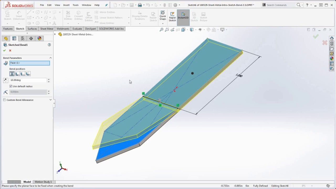
23 Solidworks How To Bend A Part Using The Sketch Bend Feature Intro To Solidworks Sheet Metal Youtube

Solidworks Sheet Metal Exercise Basics Youtube Sheet Metal Sheet Metal Drawing Solidworks

Generative Sheet Metal Design Catia I Assignment 1 I Part 1 Youtube

Bend Order In Solidworks Sheet Metal Parts Solidworks Sheet Metal Solid Works

Pin On Creo

Solidworks Sheet Metal 2d To 3d Sheet Metal Drawing Solidworks Solidworks Tutorial

Pin On Decor

Solved 3 Bend Corner In Sheet Metal Not Forming Properly Autodesk Community Inventor

Sheet Metal Understanding K Factor

Sw 3d Modeling Practice 3d Modeling Tutorial Technical Drawing Autocad Drawing

Bend Allowance Calculation Autodesk Community Inventor

What S New In Autodesk Inventor 2019 Inventor 2020 Autodesk Knowledge Network

Catia Sheet Metal Design Bend Hindi Urdu Youtube
Https D1ozhi4p59900 Cloudfront Net Files Urn Adsk Content Library 78756fcf E6f3 4184 Abdd 04afc0337a02 Classhandoutmfg225530sheetmetallikeaprowithfusion360robertsavage Pdf Expires 1609459199 Signature Dbexzkreykgvg Pbvjgrnj3gikkghyfnuolx2gunye Ugz7w2jw7rqxoeiyfibixywrsimdkfyntux51tdxlmmvfg3cksxtob1cqx9hyp37 Dpdf5egb Oe97szbiezko8t1zm6rqgun1ycetg 3d8f27k3jcetam61ejyznymymx0gsr Ao64p1suybv1ed50wu3hevbifcwicvlks4g1eyx4k4sjrowicn2towuuylfiw8wjnmfbn153wqq8zjrxzih4ntgbbthicfcunip5ljdsyf5 Dek4qil9lkwhka2mqflbxuxu3 8cza294kkliu5facj Nsm54dzjuluw Key Pair Id Apkaia22nyyfu6jzr5za

Solidworks Sheet Metal Tutorial Switch Box Youtube In 2020 Sheet Metal Drawing Solidworks Tutorial Sheet Metal

Dimensions Of A Sheet Metal Part In An Ipart Autodesk Community Inventor

Pin On Machining

Tech Tip Solidworks Spiral Sheet Metal Youtube

Start With Flat Sheet Metal Autodesk Community Fusion 360

Sheet Metal K Factor What It Is How To Measure Youtube
What S New In Autodesk Inventor 2021 Inventor 2021 Autodesk Knowledge Network
To Work With Bend Features On Sheet Metal Inventor 2018 Autodesk Knowledge Network

Solidworks Tutorial Solidworks Tutorial Solidworks Tutorial

